OBD2 Setup
This document outlines the setup procedure for the OBD2 function in the Mainline CCS Software.
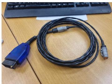
A generic “OBD2” Can cable is supplied with your dyno. This cable is a “straight thru” non electronic cable, meaning it is just a direct connection to the Vehicle CAN Bus via the OBD2 socket, there is no “electronics” inside the cable such as what there would be on an “Elm327” style of cable that would plug into a USB port or use Bluetooth. ONLY a Mainline Supplied OBD2 cable can be used and is to be plugged into the CAN 4 A or 4B sockets of the CAN hub.
The OBD2 Function in the Mainline CCS software is derived to be a somewhat “User Definable” set of PIDs to access/log from the test vehicle. A generic set of PIDs may be included with the installed software, and “installing “ is covered below.
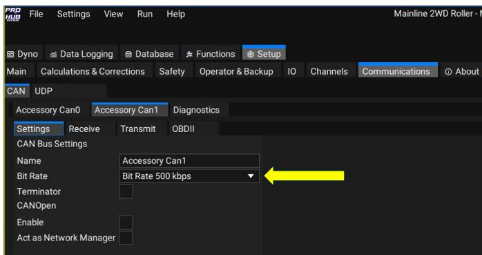
Firstly, go to the Communications Tab – Click on Accessory Can1 – Settings, and make
sure the Bit Rate is set to 500kps.
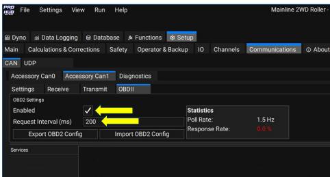
After the Bit Rate has been set on Accessory Can1, click on the Communications Tab – Accessory Can1 – OBDII.
On the OBDII tab, click the Enable check Box, set a default Request Interval to 200 ms.
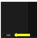
After Enabling and setting a Request Interval, click the ‘Add” button at the bottom left of
the screen:
The screen will now look like this:
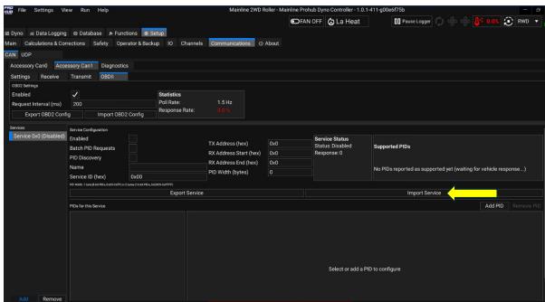
Now click the Import Service Button.
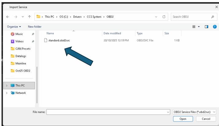
You will then be prompted to select an “OBD2 Service” set from a folder on the PC,
generally you would find the file standard.obd2svc located in the C:\Drivers\CCS folder, but it may be in the Documents folder, or you may be able to download it from the
Mainline Download Server (available March 2026), or it may be emailed to and you can
save it anywhere you wish on the Dyno PC. The example shown below the file was
located in C:\Drivers\CCS System\OBD2 for example:
Once the “Service” has been loaded, the screen will change and show the PIDs that are setup withing the “Service File”:
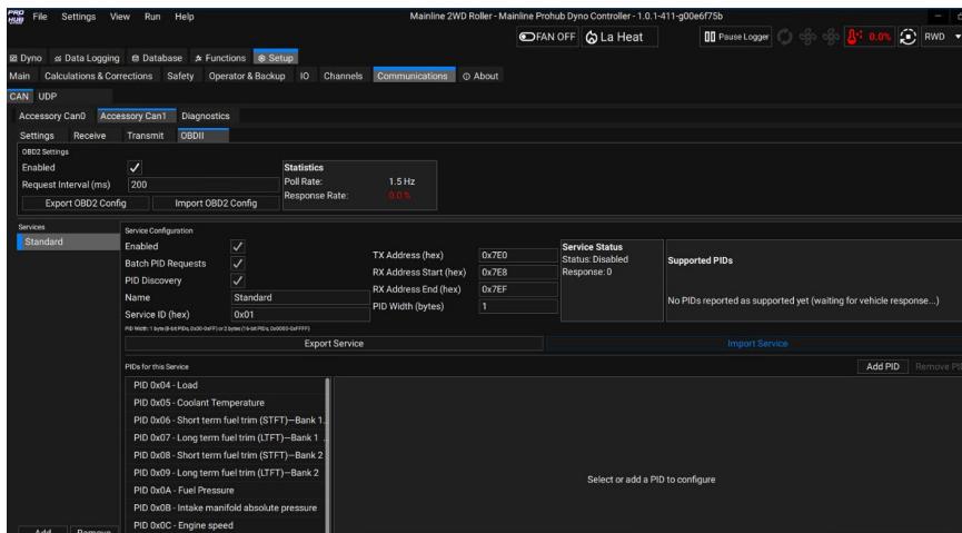
The Standard OBD2 service ?le only has the first 20 generic OBDII PIDs,
Essentially once all these steps have been completed, the Dyno Software should be polling the test vehicle CAN bus for OBDII data. The PIDs shown in the Standard Service may not be all available on the test vehicle. Once connected and polling for PIDs/Data the Supported PIDs box will show the PIDs supported by the test vehicle:
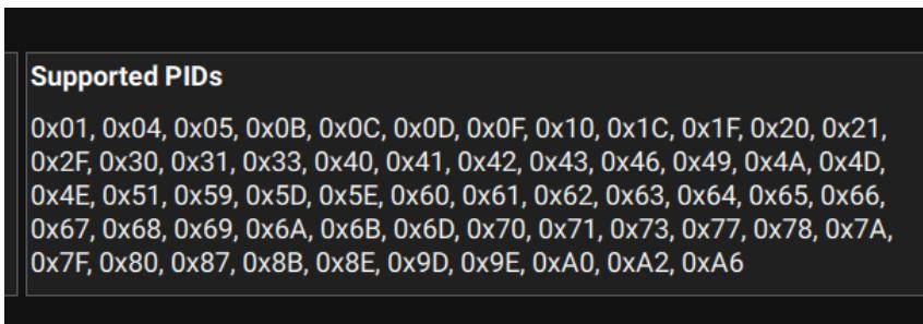
The above example is from a 2023 Ford Ranger, and many of these PIDs are well beyond the Standard Service PIDs. A user can generate their own custom OBDII “Services” for specific vehicles, and these “Services” can be Added or Removed when needed.
For best results, due to the way OBDII operates from a polling and data receive point of view, the lowest amount of PIDs “polled” will return the highest Poll rate.
Users of CCS system could if wanted, share OBDII services, as the ability certainly exists for advanced users to write OBDII Services to acquire Manufacturer Specific PIDs on Mode 21 or Mode 22 for example. The Standard Service just deals with Mode 1.
Further information on the Topic of OBDII can be found here https://en.wikipedia.org/wiki/OBD-II_PIDs
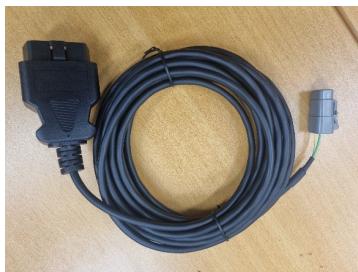
There have been 2 sorts of OBD2 cables supplied, the blue version was an earlier version where the end was removable so the cable could be used as “Generic” CAN cable, or the later OBD2 only end version: